Comparision based digital Password system using Logic gates
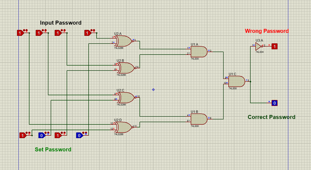
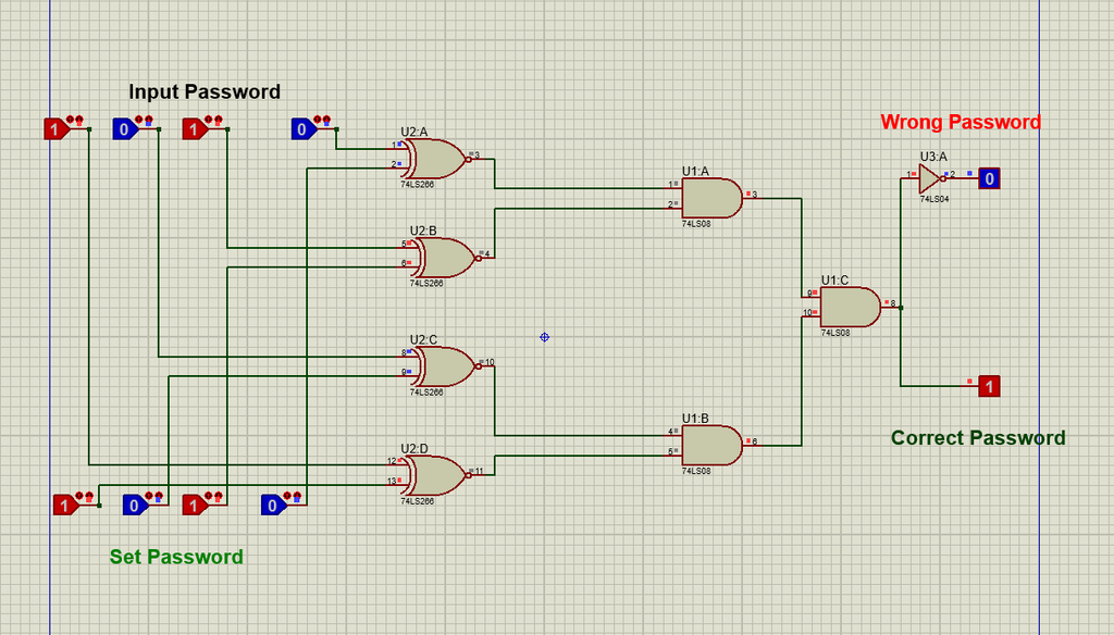
A Comparison Based Digital Password System is a such type of project in which Logic Gates are used in digital circuit for Comparing the input Password with the Early set Passwrord it provide access only when the password entered by the user exactly matches the predefined password stored in the system with the help of Logic Probes/States. The system uses logic gates, mainly XNOR, AND and Not gates, to compare the entered binary password with the stored password. Each XNOR gate compares one input bit with its corresponding stored bit and produces a HIGH output when both bits are the same.
Read More
The outputs of all XNOR gates are then connected to an AND gate, which produces a HIGH signal only when every bit matches correctly. If the complete password matches, an Access Granted LED is turned ON; otherwise, the system indicates Access Denied. This project demonstrates the practical application of digital logic gates in electronic security systems and can be implemented and tested using software such as Proteus.
Circuit diagram of Comparision based digital Password system

Components used in comparision based Digital password system
Here are the several components used in digital Compariosion based digital password system.
Logic Gates
There are three Logic gates which are used in Comparision based Digital Password system.
XNOR Gate
The 74LS266 is a quad 2-input XNOR gate IC used for comparing binary inputs in the digital password system. It contains four independent XNOR gates, and each gate gives a HIGH output when its two input signals are the same. In the password circuit, the 74LS266 compares each entered password bit with its corresponding stored password bit. If the bits match, the output is HIGH, while a difference between the two bits produces a LOW output. The outputs of the four XNOR gates are then used to determine whether the complete password is correct.
AND Gate
The AND gate is used to combine the outputs of the XNOR gates. An AND gate produces a HIGH output only when all of its inputs are HIGH. In the password system, this means that the AND gate will provide an Access Granted signal only when every individual password bit matches the stored bit. If even one bit is incorrect, one XNOR output becomes LOW, causing the AND gate output to become LOW and preventing access.
NOT Gate
The NOT gate, also known as an inverter, is used to reverse a digital logic signal. It changes a HIGH input (1) into a LOW output (0) and a LOW input (0) into a HIGH output (1). In the password system, the NOT gate can be used to invert selected password bits or logic signals when required by the circuit design. It helps generate the correct complementary signals needed for proper password comparison and control of the access indication.
Learn More in Detail About Logic Gate ( Visit )
Logic Probes/ Input buttons
used to give an inputs to the system and set the password bits in the system.
LED
The LED is used to indicate the output of the system like if the user put correct input then the LED indicates
Operation of Comparision based security Password system.
How Many Types of Basic Logic Gates?
Their are Following three Most basic Types of Logic Gates.
AND Gate
OR Gate
NOT gate
What is the IC Number Of Basic Logic Gates?
IC ( Integrated Circuit ) Number of Basic Logic Gates.
And Gate – 74LS08
NOT Gate – 74LS04
OR Gate – 74LS32
What are special Purpose and Universal Logic Gate?
Special Purpose Logic Gates are such type of Logic gates which are used for special operations Like Comparasion Between to input numbers.
XNOR- 74LS
XOR- 74LS
Universal Logic Gate are such Type of Logic Gate From Which we can create any Type of Logic Gate.
These Includes:
NAND Gate – 74LS00
NOR Gate – 74LS02