AC to DC Power conversion Circuits.
AC to Dc Conversion Using Full Wave Bridge Rectifier
A bridge rectifier is an electronic circuit used to convert AC (Alternating Current) into DC (Direct Current). It typically consists of four diodes connected in a bridge configuration. During the positive half-cycle of the AC input, two diodes conduct and allow current to flow through the load in a particular direction, while during the negative half-cycle, the other two diodes conduct and maintain the same direction of current through the load. As a result, both halves of the AC waveform are converted into a pulsating DC output. A capacitor can then be connected across the load to smooth the pulsating DC and produce a more stable DC voltage. Bridge rectifiers are widely used in DC power supplies, battery chargers, and electronic circuits.
Circuit Diagram of Bridge Rectifier
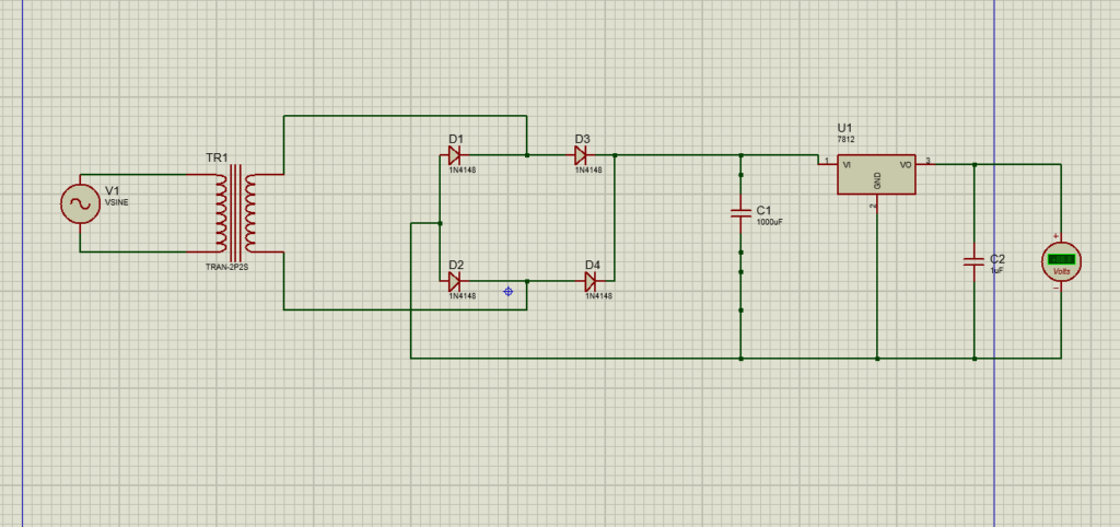
Components Used in a Bridge Rectifier Circuit
AC Power Source:
The AC power source provides the alternating voltage that needs to be converted into DC. It continuously changes its polarity and supplies the input signal to the bridge rectifier.
Diodes:
Four diodes are connected in a bridge configuration to form the bridge rectifier. They control the direction of current so that both the positive and negative half-cycles of the AC input produce current through the load in the same direction.
Load Resistor:
The resistor acts as the load of the circuit and receives the rectified output voltage. It also limits the current flowing through the circuit and provides a point where the output DC voltage can be measured.
Capacitor:
A capacitor is connected across the load to smooth the pulsating DC produced by the bridge rectifier. It charges when the rectified voltage rises and discharges when the voltage falls, reducing the ripple and producing a more stable DC output.
Voltmeter:
The voltmeter is connected across the load to measure the output voltage after rectification and filtering. It helps verify the DC voltage produced by the circuit.
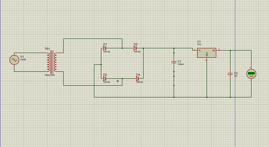
Proteas Simulation of Converting AC to DC Power Using Full wave Bridge recctifier
2-AC to DC Conversion Using Half Wave Rectifier.
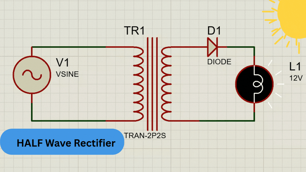
A half-wave rectifier is a basic electronic circuit used to convert AC (Alternating Current) into pulsating DC (Direct Current). It uses a single diode as the main rectifying component. The diode allows current to flow during only one half-cycle of the AC input and blocks current during the other half-cycle. As a result, only one half of the AC waveform appears across the load.
Circuit Diagram of Half Wave Rectifier
How Do Ac to Dc Rectifier Works?
During the positive half-cycle of the AC input, the diode becomes forward biased and conducts current. The current flows through the diode and load resistor, producing a positive voltage across the load.
During the negative half-cycle……..
the diode becomes reverse biased and blocks current. Therefore, almost no current flows through the load, and the output voltage is approximately zero during this half-cycle.
The resulting output is therefore a pulsating DC waveform consisting of only the positive (or negative, depending on diode orientation) half-cycles of the input AC signal.