Traffic Signal system Using Arduino and LCD Display
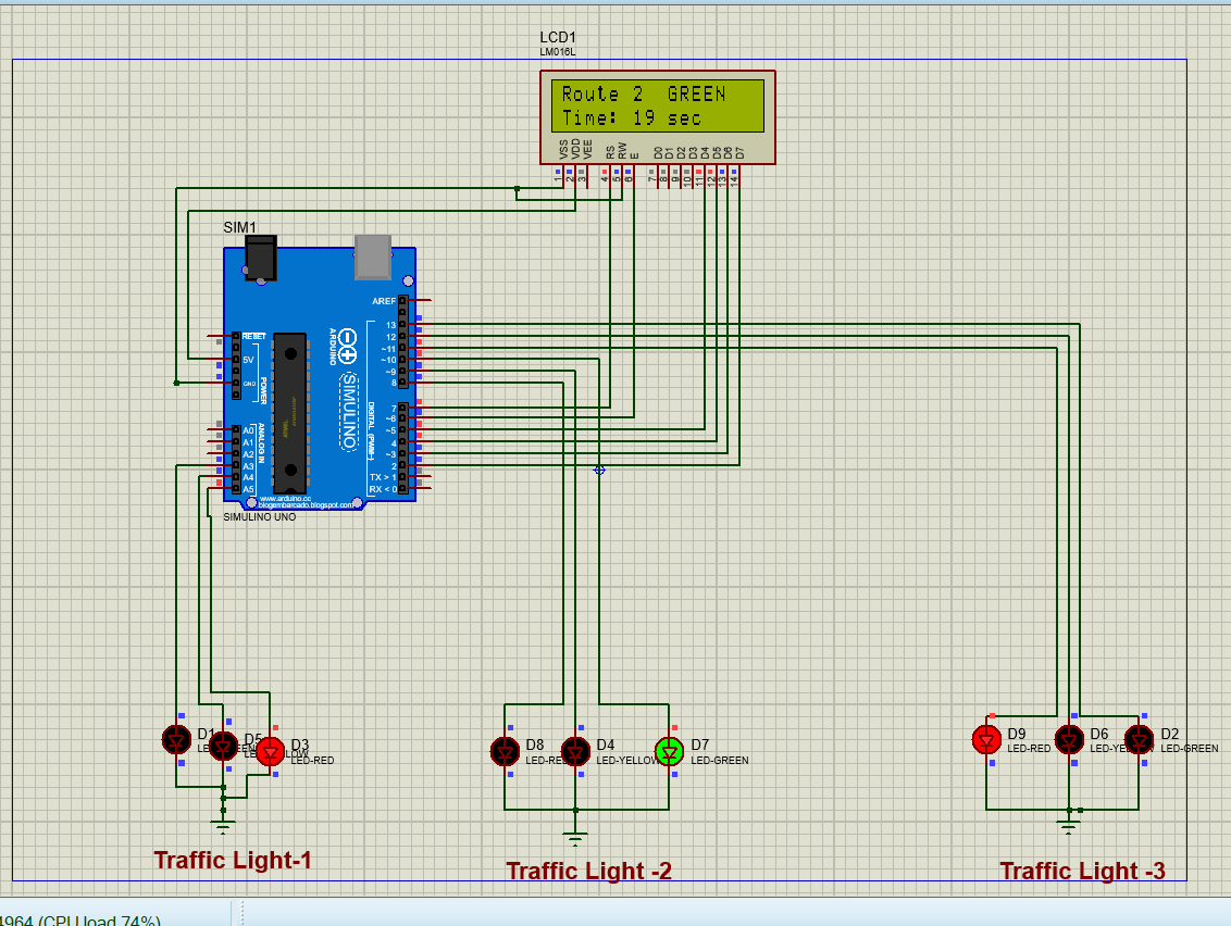
The 3-Way Traffic signal System Using Arduino starts with all three routes in the red-light condition, ensuring that traffic is initially stopped on every route. After the initial condition, the Arduino activates the green light of Route 1, while Routes 2 and 3 remain red, allowing vehicles on Route 1 to move. Each route is given a total of 20 seconds. During the first 12 seconds, the active route displays a green light, and when the timer reaches 8 seconds, the green light changes to yellow.
Read in Detail
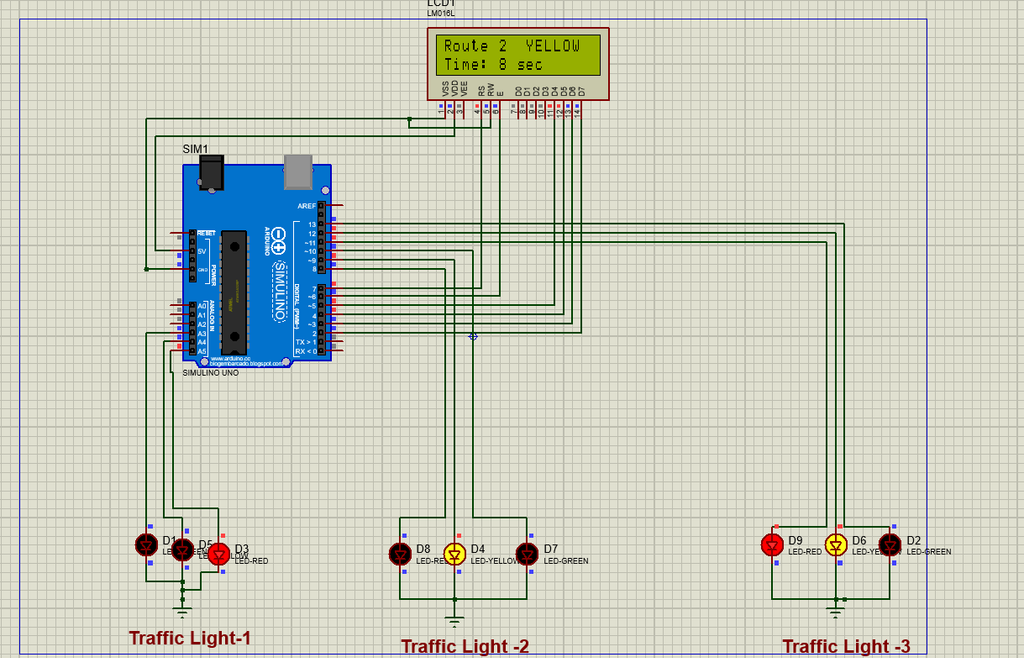
During these final 8 seconds, the yellow light of the current route warns vehicles to slow down and prepare to stop. At the same time, the yellow light of the next route is also activated as a transition indication. When the countdown reaches zero, Route 1 changes to red and Route 2 immediately changes to green, allowing traffic on Route 2 to move.
The same process is then repeated for Route 2: it remains green for the first 12 seconds, changes to yellow for the final 8 seconds, and the yellow signal of Route 3 is activated as a warning that Route 3 will become active next. When Route 2 reaches the end of its 20-second cycle, it changes to red and Route 3 changes to green. Finally, Route 3 follows the same sequence, with 12 seconds of green and 8 seconds of yellow, while the yellow signal of Route 1 is activated during the transition period.
Once Route 3 reaches zero, it changes to red and Route 1 becomes green again, completing one full 60-second traffic signal cycle. An LCD display continuously shows the active route, current signal status, and remaining time, allowing the operation of the system to be monitored easily. In this way, the Arduino controls the three routes in a continuous and organized sequence while preventing conflicting green signals.
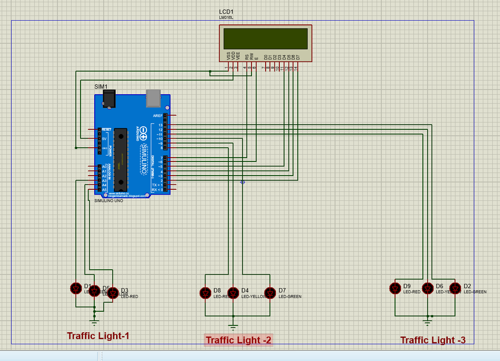
Circuit diagram of Three way Traffic Signal system
Components Used in Traffic Light system
Here are several components used in Traffic Signal Control system.
Softwares used to create Trafic control signal system
Proteas Simulation Environment
The Proteus simulation environment provides a virtual testing platform for the project. Instead of physically connecting an Arduino and traffic lights, the complete system can be tested digitally. This makes it possible to verify the timing sequence, LED operation, LCD display, and transitions between the three routes. Any connection or programming errors can also be identified and corrected before constructing the actual hardware circuit.
Arduino IDE
The Arduino IDE (Integrated Development Environment) is used to write, edit, compile, and upload the C/C++ program for the Arduino UNO. In this project, the Arduino IDE is used to develop the traffic signal control program, including the timing sequence, LED control, and LCD operation. The program defines the Arduino pins connected to the red, yellow, and green LEDs and controls them according to the 20-second cycle for each route. After the code is compiled successfully, the generated program file can be used with the Arduino model in Proteus for simulation.
Components used in Circuit of Traffic Light system
Arduino UNO
The Arduino UNO is the main control unit of the traffic signal system. It is responsible for controlling all nine traffic LEDs according to the programmed timing sequence. The Arduino activates the green, yellow, and red signals for each of the three routes and ensures that the routes operate in the correct order. In the Proteus simulation, the Arduino UNO executes the uploaded program and controls the connected LEDs and LCD display.
Resistor
Resistors are used in series with the LEDs to limit the current flowing through them. This protects the LEDs and the Arduino’s output pins from excessive current. In a Proteus simulation, a resistor such as 220 Ω can commonly be connected in series with each LED.
LED Lights
LED (Light Emitting Diode) is an electronic semiconductor device that produces light when electric current flows through it in the forward direction. LEDs are used in this project as visual indicators to represent the traffic conditions of the three different routes. Since each route requires three different traffic conditions—Stop, Prepare to Stop, and Go—three types of colored LEDs are used.
Yellow LED – Warning / Prepare to Stop
The yellow LED represents the warning or transition condition. It is activated during the final 8 seconds of a route’s 20-second cycle. During this period, the current green light changes to yellow, indicating that vehicles should slow down and prepare to stop. In your design, the yellow signal of the upcoming route can also be activated during the transition to indicate that the next route is about to become active.
Green LED – Go
The green LED represents the GO condition. When the green LED is ON, vehicles are allowed to move through that route. Each route receives 12 seconds of green time, followed by 8 seconds of yellow time. After the 20-second cycle is completed, the green LED turns OFF and the route changes to red.
RED LED
The red LED represents the STOP condition. When the red LED is ON, vehicles on that particular route are not allowed to move. In the three-way traffic system, the routes that are not currently active have their red LEDs switched ON. This ensures that traffic from different routes does not move simultaneously.
16×2 LCD Display
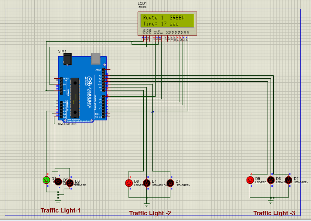
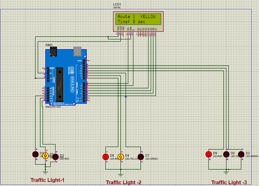
The 16×2 LCD display provides a visual indication of the traffic signal operation. It displays the currently active route, its signal status, and the remaining time. For example, the LCD can display “Route 1 GREEN” and “Time: 15 sec”. As the countdown continues, the displayed time decreases every second. When the timer reaches 8 seconds, the display changes from GREEN to YELLOW.
Traffic control Signal system simulation

Code of Traffic control Light system using Arduino Microcontroller
Here is the C++ code of Traffic control signal system .