Home Automation DIY Projects Using Arduino Microcontroller.
1-Obstacle Detector using Arduino board-DIY project.
An obstacle detector is a such type of project which detects an objects when ever an object comes to its path. Basically this project is a prototype of a blind man stick which will helps the blind people from being hit by any type of obstacles. it will alert the person from barriers which comes in to their pathway.
Working and Operation
In our project it reads The data fetched by the Ultrasonic Sensor and perform actions according to the code written on it.
The Arduino UNO AVR works as a brain on our project.
when the ultra sonic sensor detects any object in the distance of 10 cm or less ( as per assigned in the code) it will operate and give the signal to the Arduino.
The Arduino reads the signal and trigger the buzzer (as per the code written on it ). when ever the Buzzer beeps the led will also glow.
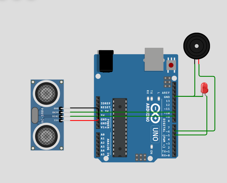
Components used in Obstacle detection system.
Here are several components used in Obstacle Detection System Using Arduino Microcontroller.
Arduino Uno
In this Project Arduino acts as the brain of the ystem. The ultrasonic sensor measures the distance between the system and an object, while Arduino receives and processes this distance information. The sensor sends an ultrasonic pulse through its TRIG pin, and when the pulse hits an obstacle, the reflected signal returns to the ECHO pin.
Arduino measures the time taken for the signal to return and calculates the distance using the speed of sound. If the measured distance becomes less than a predefined safety limit, Arduino recognizes that an obstacle is present and can take an appropriate action, such as turning on an LED or buzzer, stopping a motor, or changing the direction of a robot. In this way, the ultrasonic sensor performs the detection, while Arduino performs the processing, decision-making, and control of the system.
What are Arduino Boards?
Arduino boards are a small programmable circuit board with a microprocessor on it. These are essentially a tiny computer on which we write a program in programming language (c++). Arduino Boards are so popular due to how approachable it is. The programming language is simple, the boards are affordable, and the online community is enormous.
Ultrasonic Sensor
The ultrasonic sensor detects obstacles and measures their distance. It sends ultrasonic waves and receives the reflected waves. The sensor then provides the distance information to the Arduino, which uses it to determine whether an obstacle is nearby.
How Ultrasonic Sensor Works?
An ultrasonic sensor works by using high-frequency sound waves to detect objects and measure distance. First, the sensor sends an ultrasonic pulse through its transmitter. These sound waves travel through the air and, when they hit an object, they are reflected back toward the sensor. The sensor receives the reflected waves through its receiver. It measures the time taken for the sound wave to travel to the object and return.
Using this time and the speed of sound, the distance between the sensor and the object can be calculated. This process happens very quickly and can be repeated continuously, allowing the sensor to detect moving or stationary objects. Ultrasonic sensors are commonly used in obstacle detection, parking systems, robotic vehicles, automatic doors, water-level measurement, and distance-measuring systems.
LED
The LED provides a visual warning when an obstacle is detected. When the ultrasonic sensor detects an object within the set distance, the Arduino turns the LED ON. When no obstacle is detected, the LED remains OFF.
Buzzer
The buzzer provides an audio warning when an obstacle is nearby. When the ultrasonic sensor detects an object within the defined distance, the Arduino activates the buzzer, producing a sound to alert the user.
Pin connection of ULtrasonic sensor and the
Arduino (UNO)
| Ultrasonic Sensor Pin | Arduino UNO Pins |
| VCC | +5 v |
| GND | GND |
| ECHO | D-10 |
| Trigger | D-9 |
2-DIY Project LED Upcounter using Arduino Microcontroller
In this project we will try to create an up counter using Microcontroller. in counters the LED’s starts to glow in right or left direction respectively. The LED’s start to glow when we push a button the time delay will be set according to the need.
Circuit design of the Up counter using Arduino Uno
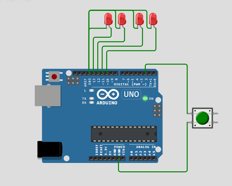
Brief Description of the working of Upcounter using Arduino Uno.
When we push the Button then the LED’s will start to glow and moves from left to right. after completing one cycle all the LED’s will turn off for Mili Seconds ( according to need).then again they start to glow rom left to right respectively.
Here is the practical demonstration of upcounter using Arduino board.
3-LED controlling by two bit binary system
In this project will control the LED’s by the process of 2 bit Binary number system using Arduino UNO. To gai a desired out put from any type electronic components we use high and low signal to pass the instructions and command on the basis of which the electronic components perform actions.
Binary Number system
Binary numbers are such type of numbers which are represented in the form of zeros and one’s (0s, 1s) it represents the high and low signals or ON and OFF State. It is one of the Most Significant way to give instructions to computers and to process the data. Electronic machines operates on the principles of binary numbers they do not understand any other language rather then binary so that’s why the binary number system is called the Universal Number System of Computers.
As we know that the electronic components understand only one that is binary when ever any component receive high signal it is considered as 1 and when it receives low signal it is considered as 0 by this way a whole system works.in this project will operate the LED signals by giving high and low signal with the help of two dip/ toggle switches. this switches will be considered as the two bit binary inputs.
Understand the concept of Number system
The number System are defined as the method of representing numbers in different way with different Symbols are Known as Number system. There are several ways to represent Number System which includes Octal, Binary, decimal and Hexadecimal.
The system will works on the basis of the binary inputs as shown in the table.
here is the Table of Binary Input.
| LED-1 | LED-2 | LED-3 | Led-4 | |
| Sw-0 | 0 | 1 | 0 | 1 |
| Sw-1 | 0 | 0 | 1 | 1 |
Circuit diagram of Led controlling by two bit binary input.
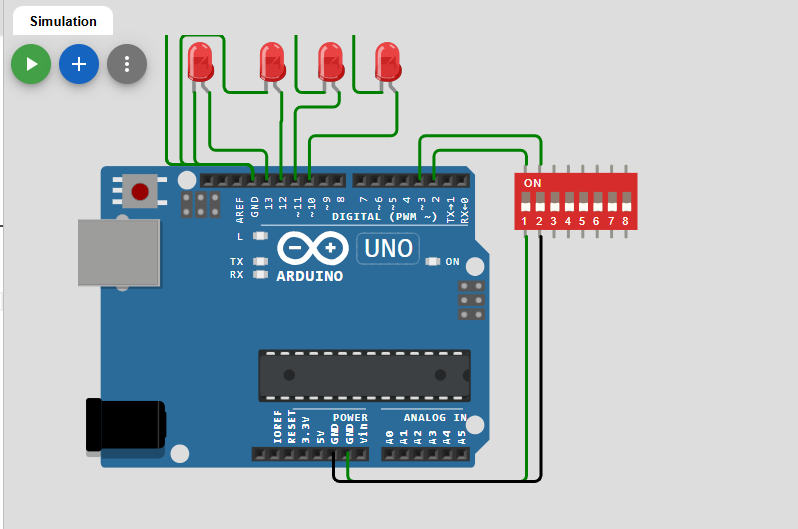
Watch video to understand and design the Bit wise LED controlling using microcontroller.
FAQ Section (Frequently Asked Questions)
What is the difference between the microcontroller and microprocessor?
A Microprocessor acts just like a brain of a Computer its function is only to process the task or helps the computers to operate any functions. while the microcontrollers are such type of components which has build in memory, RAM, ROM and processor these are used to perform special tasks like used in embedded systems
What is a microcontroller?
A microcontroller is a compact integrated circuit that contains a CPU, memory (RAM, ROM/Flash), and input/output peripherals on a single chip.
It is designed to Perform specific tasks in embedded systems.
Examples of Microcontrollers:
Esp-32,Jatson Nano,
ATmega328P, PIC, 8051
What is a Microprocessor?
A microprocessor is an integrated circuit that contains only the CPU. It requires external memory (RAM, ROM) and peripherals to function.
Examples of Microprocessors:
Intel processors ( 8085 and 8086 series )
AMD processors