Here you will get Practical based Electrical Engineering Projects and i definitely say that after going through you must be able to build you own Project circuits.
Project-1:LED brightness control using potentiometer.
The brightness of an LED can be smoothly controlled using a potentiometer, making it a simple and practical electronics project for understanding variable resistance and LED control.
Read More
In this project, the potentiometer is used to vary the voltage or control signal supplied to the LED, which changes the amount of current or PWM signal controlling its brightness. By slowly rotating the potentiometer in one direction, the LED can gradually become brighter, while rotating it in the opposite direction reduces its brightness. This provides smooth and precise control rather than simply switching the LED on or off.
Circuit diagram of LED controlling by Potentiometer.
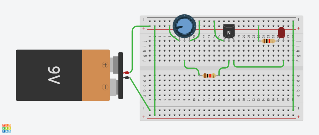
Components used in Led brightness control
Here are the several components which are used in LED Brightness controlling.
Transistor
Transistors are an electronic components used for switching, Amplification, Signal control and voltage regulation in an electronic circuit.
Potentiometer
It is a variable resistor used to control electrical signals by changing its resistance increase or decrease.
Resistor
A Resistor is passive element which is used to control the flow of electric current.
LED
Led’s are widely used in electronic circuit it changes electrical energy in to light energy.
LED Brightness Control using Potentiometer video
Project-2 : Digital password security system using logic gates
The Digital security Password system is a such type of system which uses logic gates to provide an interface in which it allows a person to enter an inputs password in binary form that input will be compared to the internal set numbers by the user as a Password.
Read More
This system will allow the user to create and update password. It also allow the users to change the password. When the user Enters the password correct then the upper Logic probe at the output shown in the figure below will display 1.
In case of wrong password the lower Logic Probe will be equal to 1 instead of it will remain 0. The 0 and 1 Logic Probes indicates the result of the input password.
Components used
Logic gates
logic gates are an electronic circuit used in digital electronics to make a logical decision. They takes one or more binary inputs(high or Low signal) and give us an output.
There are Two types of Logic gates.
- Basic Logic Gates
- Special Purpose Logic Gates
Toggle Switches / input Probes
Through these switches we can be able to Input password and the set Password.( in Binary Language)
Here is the internal structure of the security system.
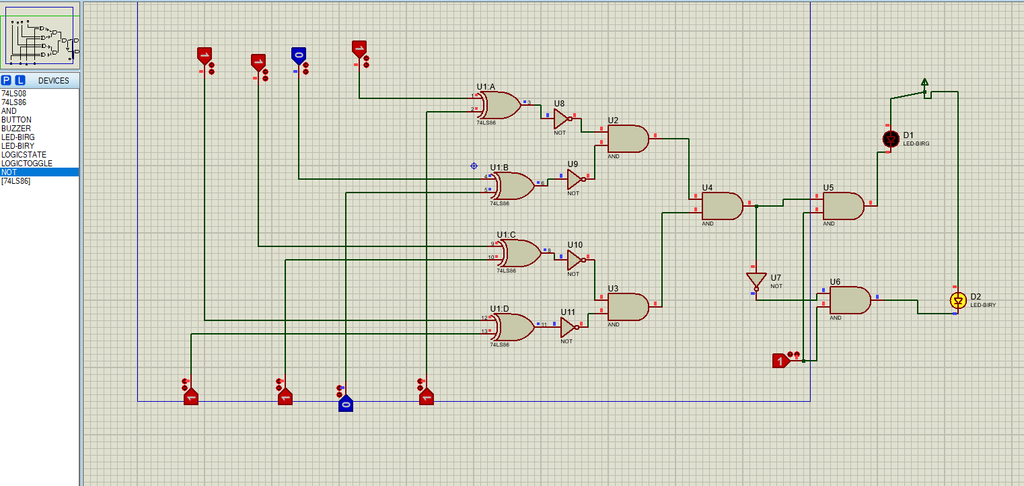
Password set
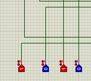
Input Password Probes

Components used in Digital Password System
- LogiStates
- LogicProbes ( LED or Buzzer )
- XNOR Gates ( 74LS266 )
- AND GATE ( 74LS08 )
- NOT GATE ( 74LS04 )
The Image below shows that how can we change the password.
3 – BCD to seven segment Decoder using proteas
In this project we will convert the binary coded numbers into seven segment LED’s. The BCD to 7-Segment Decoder is an electronic circuit device which is used to convert the Binary numbers into Decimal Numbers from Zero to Nine (0-9) with the help of Seven Segment LED Display. The LED’s are assembled in such format that when ever they glow they represents Decimal Number from 0 to 9.
Circuit Diagram and Implementation of BCD to Seven Segment Decoder in Proteus.

7-Segment Display
Seven segment Display is an electronic device which is used to display the decimals numbers from 0 to 9 in a circuit board. It shows the numbers by glowing and LED’s in a such format that they represent decimal numbers.(See simulation Based Projects visit)
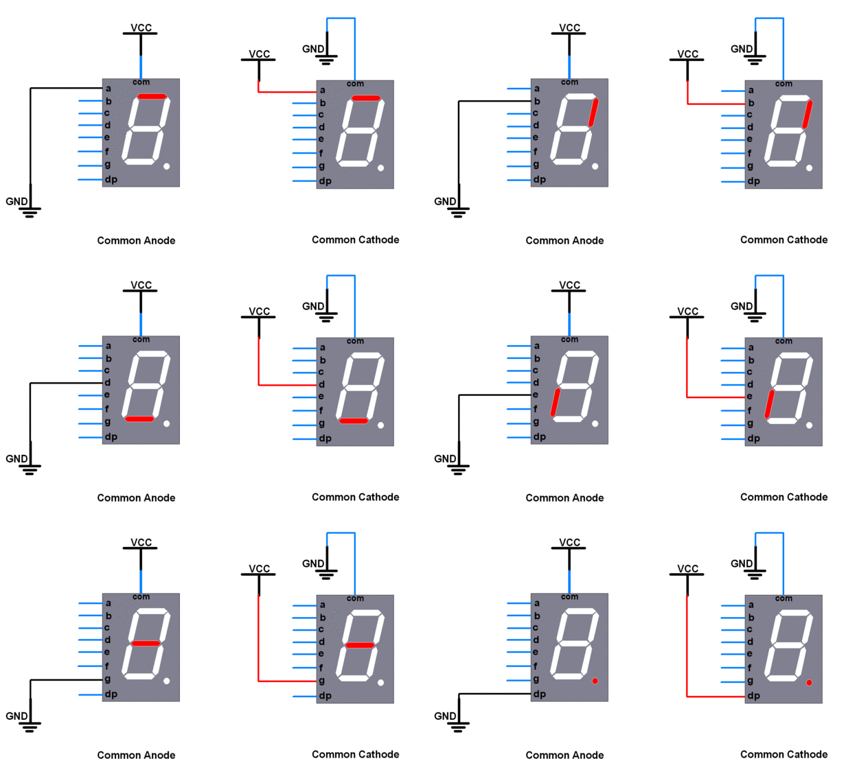
Components used to convert BCD to 7-segment Display
- Logic States
- BCD to 7segment Decoder (74LS47)
- Resistors (220 – 310 Ohm)
- 7segment display
- Vcc ( 5v )
- Ground (Gnd)
FAQ (Frequently Asked Questions ) :
What is the IC Number of XNOR Gate?
The IC No# of XNOR Gate is 74LS266.
What is the IC Number of NOT gate?
The IC Number of NOT gate is 74LS04
What is the Function of XNOR gate?
The XNOR gate is used to compare two inputs. If both of the inputs of the XNOR gate are same then it’s output will be equal to 1. Other wise the output will stay 0.
eg.
1, 1 = 1
0, 0 = 1
1, 0 = 0
0, 1 = 0
What are the Practical Usage of Logic Gates?
The electronic components can not be able to understand the language of humans. with the help of logic gate we create such type of system under which the computers become able to understand and obey the commands of humans these all are done by the help of using logic gates.
1: What is Decoder?
Decoder is an electronic circuit which is used to convert some lines into many lines. For example : BCD to seven segment decoder.
2-What is an Encoder?
Encoder is a combinational circuit which is used to convert many lines to some lines. Basically it converts the large number of data lines into few lines.
Example: Binary encoder
What are BCD numbers?
The BCD stands for binary coded decimal numbers. which contain 16 bits from 0 to 15. The bits from 0 to 9 are called the valid bits or valid numbers and from 10 to 15 are called invalid numbers. The number 10,11,12,13,14,15, represented by A,B,C,D,E, and F respectively.
What is the Difference between MOSFET and BJT??
MOEFET is voltage controlling device used for switching in a circuit while the BJT (Bipolar junction Transistor) is current controlling device used for small amplification like so that’s why we prefer Mosfet rather then BJT..
Why the Transistor is used in the circuit to control the brightness of LED if we can directly control LED’s by Potentiometer?
Because when we use a larger LED then at the time we should need larger current at that case the potentiometer can not be able to control the high current so that why we use transistor.