Here we will discuss about best Electronic and embedded systems projects step by step form simulation to run on hardware. in the field of electrical engineer now a days microcontrollers plays a very crucial role they brought a huge change in electronics and given a new shape to the field of electrical engineering.
1-Night Detection Lightening system Home automation Project.
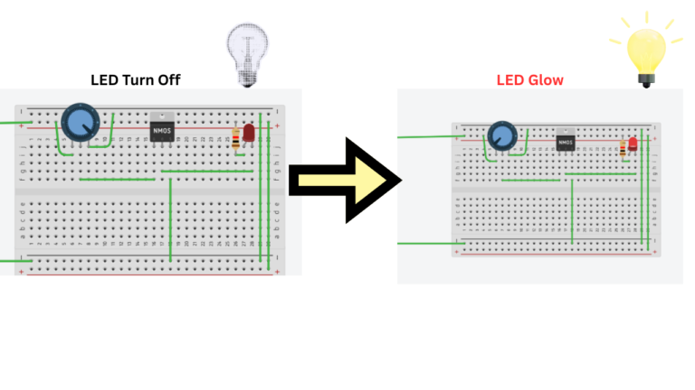
A Night Detection Lighting System is an automatic lighting system that detects the surrounding light level and turns a light ON when it becomes dark and OFF when sufficient light is available. This type of system is commonly used for automatic street lights, garden lights, security lights, and other outdoor lighting applications.
The system can be built using a photoresistor (LDR), which is a light-sensitive electronic component. The resistance of an LDR changes according to the intensity of light falling on its surface.
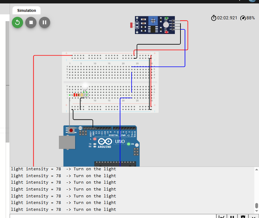
Circuit Diagram of Night Detection Lightening System
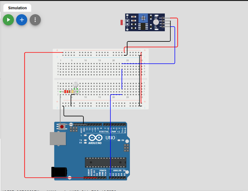
Components used in Night Detection Lightening System
Arduino Uno
The Arduino Uno is a popular microcontroller development board based on the ATmega328P microcontroller. It is widely used in electronics, automation, robotics, and sensor-based projects because it is simple to program and easy to connect with different electronic components.
The board provides digital and analog input/output pins, which allow it to receive signals from sensors and control devices such as LEDs, motors, relays, and buzzers. It can be programmed through the Arduino IDE using a simplified version of C/C++. (To Learn More About Microcontroller Visit Site)
Photoresistor (LDR)
A Photoresistor, also known as a Light Dependent Resistor (LDR), is a light-sensitive electronic component used to detect changes in the intensity of surrounding light. Its resistance changes according to the amount of light falling on its surface: when the light intensity increases, its resistance decreases, while in darkness or low light, its resistance increases.
Structurally, an LDR consists of a photosensitive semiconductor material placed between two conductive terminals and usually covered with a protective transparent or translucent casing that allows light to reach the sensing material. The LDR is commonly connected with another resistor to form a voltage divider, producing a voltage that can be measured by a microcontroller or other electronic circuit.
Led Bulb
It is an electronic component which is used to give brightness or light in surrounding. the LED Bulbs are Less Energy consumption components. They save a lots of energy consumption then the other conventional used Bulbs
Working of Dark/Night Detection Lightening System
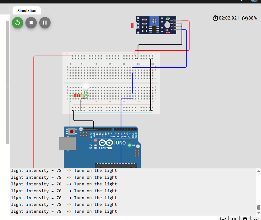
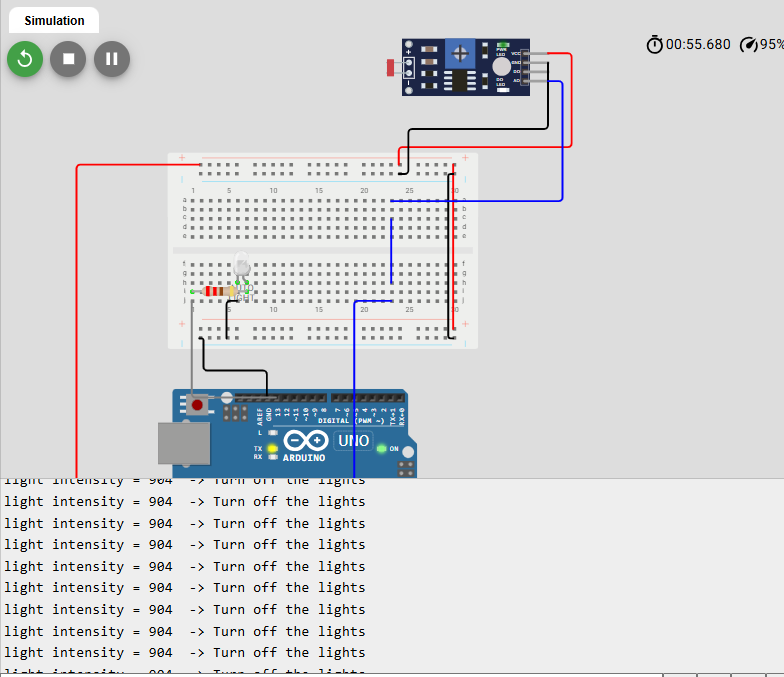
Download the code of Night detection system project from given link Below
2-Home automation Project :Automatic Gas Leakage System using Esp-32 Microcontroller.
The Automatic Gas Leakage Detection System using ESP32 Microcontroller is a safety project designed to detect the presence of potentially harmful or combustible gases in the surrounding environment. The system uses an MQ-series gas sensor to continuously monitor the air. The sensor produces an analog signal according to the detected gas level, which is read and processed by the ESP32 microcontroller.
Read More
A predefined gas detection limit is set in the ESP32 program. Under normal conditions, the sensor reading remains below this limit and the system stays inactive. When the gas level increases and the sensor reading crosses the set threshold, the ESP32 recognizes it as a possible gas leakage and activates a buzzer to provide an immediate warning.
Here is the Circuit Diagram of Gas Leakage System
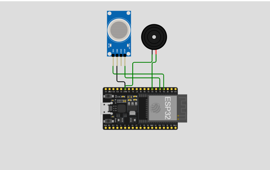
Components used in Gas Leakage detection system
Here are the several components used in gas Leakage system
Esp-32 Microcontroller
The ESP32 is a powerful microcontroller widely used in IoT, robotics, automation, and embedded systems. It provides multiple GPIO pins, an ADC for reading analog sensors, and built-in Wi-Fi and Bluetooth.
In this gas leakage project, the ESP32 reads the analog signal from the MQ gas sensor and compares it with a predefined gas-level limit. If the reading exceeds the limit, the ESP32 activates the buzzer to alert the user.
MQ-Gas Sensor
The MQ gas sensor is the main sensing component used to detect the presence of gases in the surrounding environment. Different MQ sensors are designed to detect different gases; for example, the MQ-2 can detect gases such as LPG, methane, propane, hydrogen, and smoke.
The sensor’s electrical resistance changes when it comes into contact with certain gases. The sensor module converts this change into an output signal, which is read by the ESP32.
Buzzer
The buzzer is used as an audio alarm in the gas leakage detection system. When the MQ gas sensor detects a gas level above the predefined limit, the ESP32 activates the buzzer to alert the user.
Here is the Gas Sensor detection readings and system Behavioue
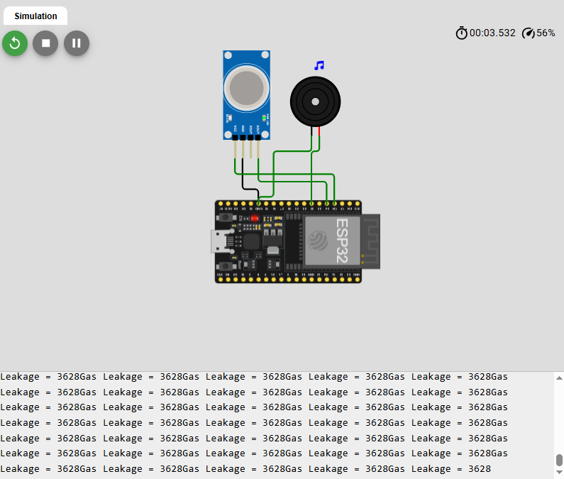
Check the Code of the Gas leakage detection system
3-Home Automation Projects: Motion Alert Detection System using Arduino and PIR sensor
It is an electronic project designed to detect the movement of a person within a specific area. The system uses a PIR (Passive Infrared) motion sensor to detect changes in infrared radiation caused by the movement of humans or other warm objects. When motion is detected, the PIR sensor sends a HIGH signal to the Arduino. The Arduino processes this signal and activates an output such as a buzzer, LED, or alarm.
Read More
In this project, the buzzer can be programmed to continuously produce a sound while motion is detected, making the system useful for basic security and intrusion-alert applications.
Working Principle
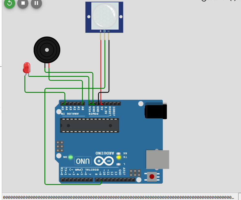
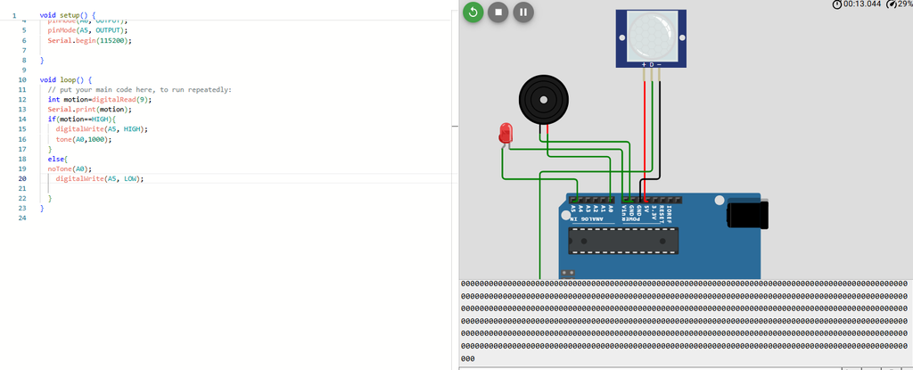
The PIR sensor is connected to one of the Arduino’s digital input pins. When there is no movement, the sensor normally provides a LOW signal. When a person enters its detection area and moves, the sensor detects the change in infrared radiation and changes its output to HIGH. The Arduino reads this signal using digitalRead().
If the signal is HIGH, the Arduino activates the buzzer using the tone() function and can also turn on an LED. When motion is no longer detected, the Arduino stops the buzzer using noTone() and turns the LED off.
Here is the Circuit Diagram of Motion Detection System
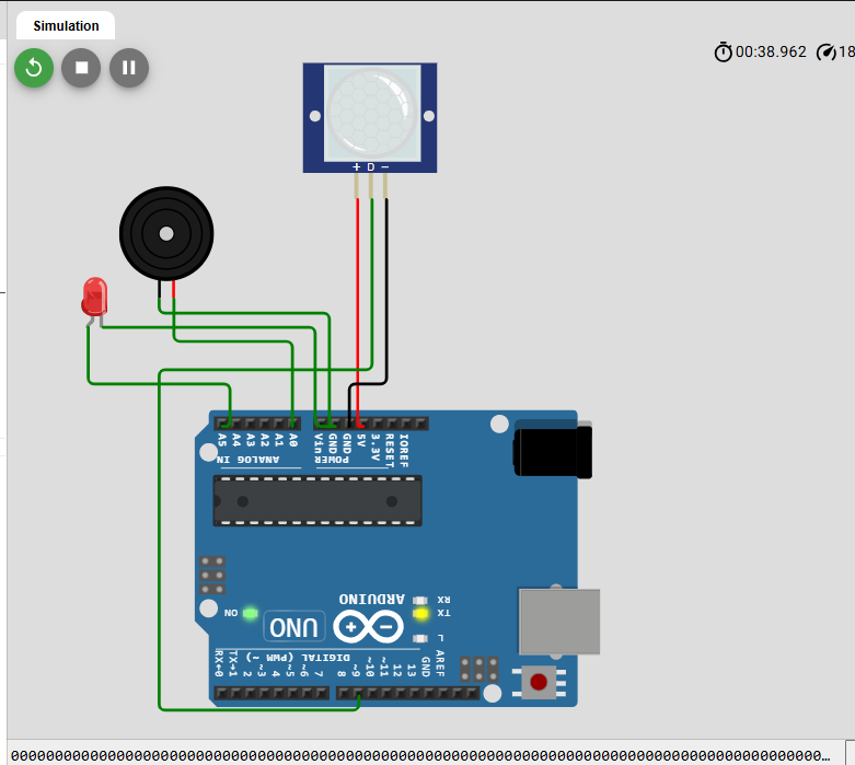
Components Used in Motion Detection System
Arduino UNO
A Microcontroller Board Which Perform all the Activities of the System Like getting Data from sensor and controlling all the out put elements i.e. LED, Buzzer etc.
Passive Infrared Sensor
A PIR (Passive Infrared) motion sensor is an electronic sensor used to detect the movement of people, animals, and other objects that emit infrared radiation. The word passive means that the sensor does not transmit any signal or energy itself; instead, it detects the infrared energy naturally emitted by objects. A common PIR module, such as the HC-SR501, contains a pyroelectric sensing element, a Fresnel lens, and an electronic processing circuit. The Fresnel lens focuses infrared radiation from the surrounding area onto the pyroelectric sensor.
When a person or warm object moves across the sensor’s detection area, the amount of infrared radiation reaching the sensing element changes. The pyroelectric element detects this change and generates a small electrical signal, which is amplified and processed by the sensor’s internal circuit. The module then produces a digital output, usually HIGH when motion is detected and LOW when no motion is detected. The Arduino can read this output through a digital input pin and perform an action such as turning on an LED, activating a buzzer, or triggering an alarm.
The HC-SR501 typically has a detection range of up to approximately 7 meters and a detection angle of around 110°, although the actual range depends on the sensitivity setting, environment, and movement of the object. It also commonly provides adjustable sensitivity and time-delay controls, allowing the user to modify how far it detects motion and how long its output remains active. PIR sensors are widely used in security systems, automatic lighting, home automation, intrusion detection, and motion-activated alarms because they are inexpensive, low-power, and relatively simple to interface with microcontrollers such as Arduino.
LED / Buzzer
Output Components used to Alert the owner by glowing and making beeps.
Simulation of the Motion Detection System
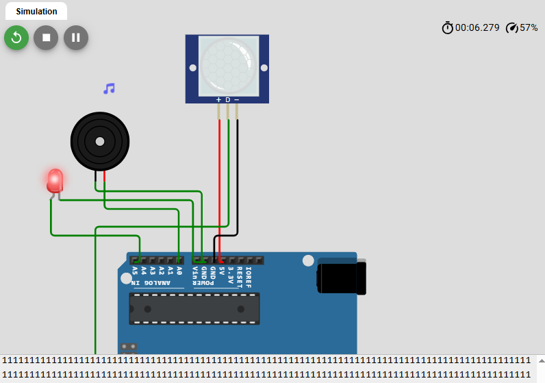
C++ Code of motion Detection system
Here is the Arduino code of the Motion detection system.
Motion detection system using Arduino microcontroller
4- Automatic car Parking system using Arduino
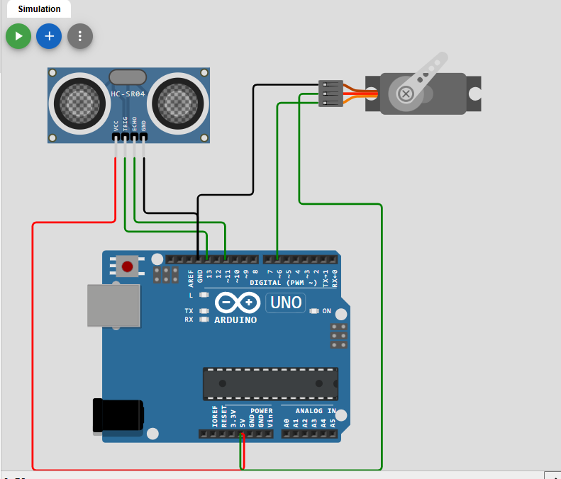
An Automatic Car Parking System detect the presence of a vehicle and automatically control access to a parking area. The system commonly uses an ultrasonic sensor to measure the distance between the sensor and an approaching car. When the vehicle comes within a specified range, the Arduino processes the sensor data and sends a control signal to a servo motor, which acts as a parking gate barrier and rotates to allow the vehicle to enter. When the vehicle moves away or is no longer detected, the servo returns to its original position and closes the gate.
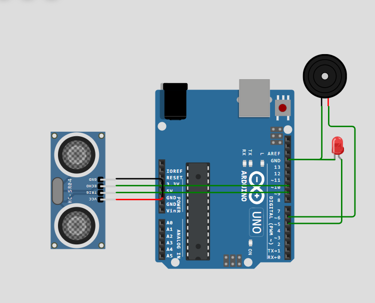
Circuit Diagram of Automatic Car Parking System
Components used
Ultrasonic Sensor
An ultrasonic sensor is an electronic device used to detect objects and measure the distance between the sensor and an object by using high-frequency sound waves. A common ultrasonic sensor, such as the HC-SR04, works by transmitting ultrasonic sound waves, typically around 40 kHz, through its transmitter. These sound waves travel through the air, hit an object, and are reflected back toward the sensor.
The receiver detects the reflected wave, known as the echo, and the microcontroller calculates the distance by measuring the time taken for the sound wave to travel to the object and return. The distance is calculated using the speed of sound and dividing the total travel distance by two because the wave travels both to the object and back. The HC-SR04 typically measures distances from approximately 2 cm to 400 cm.
Servo Motor
A servo motor is an electromechanical device used to control the position and angular movement of a shaft with high accuracy. Unlike a normal DC motor that rotates continuously, a standard servo motor can be controlled to move to a specific position, such as 0°, 45°, 90°, or 180°. A typical servo motor has three connections: VCC for power, GND for the ground connection, and a signal pin that receives control pulses from a microcontroller such as an Arduino.
The Arduino controls the position of the servo by sending PWM control pulses, where the width of the pulse determines the angle of rotation. For example, a pulse of approximately 1 ms can correspond to 0°, 1.5 ms to 90°, and 2 ms to 180°, although the exact values may vary between servo models. Servo motors are widely used in robotics, automatic doors, robotic arms, automatic parking gates, obstacle detection systems, and other automation projects because they provide simple and precise position control.
Arduino UNO
The Arduino Uno is a 5V microcontroller board based on the ATmega328P. It reads sensor data and controls components such as LEDs, motors, buzzers, and servo motors, making it widely used in robotics, automation, and electronics projects.
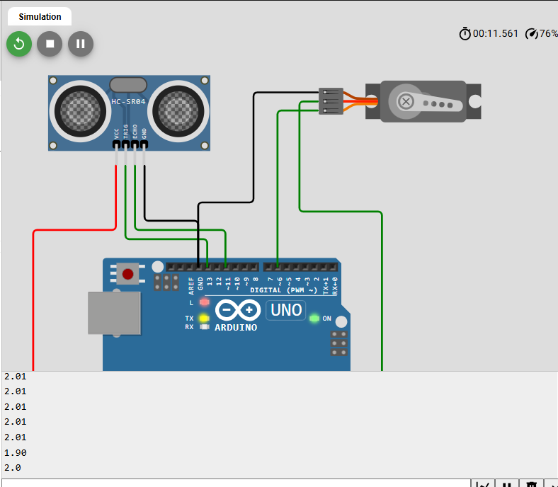
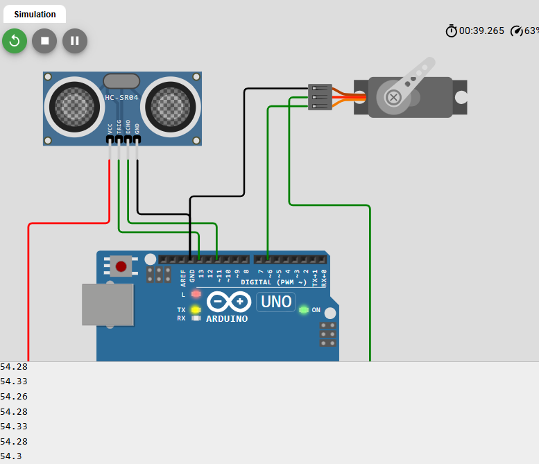
Arduino Code of Automatic Car Parking system is Given below.
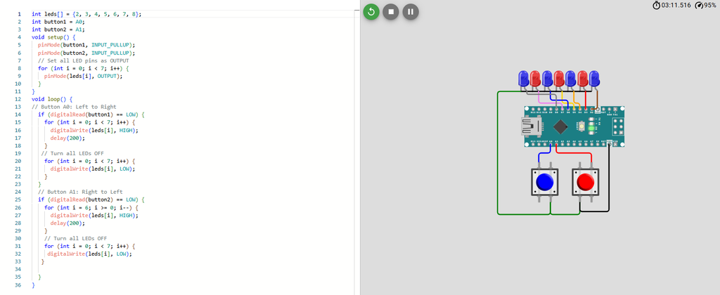
5- Led Left and Right Shifter using Arduino Nano
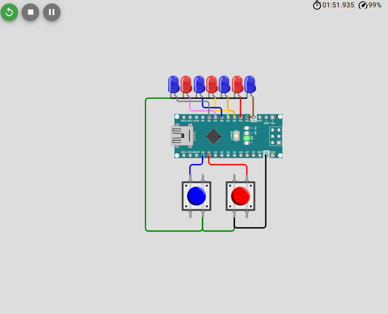
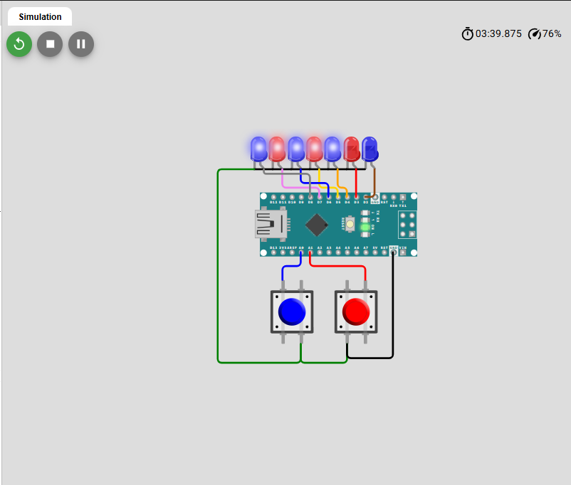
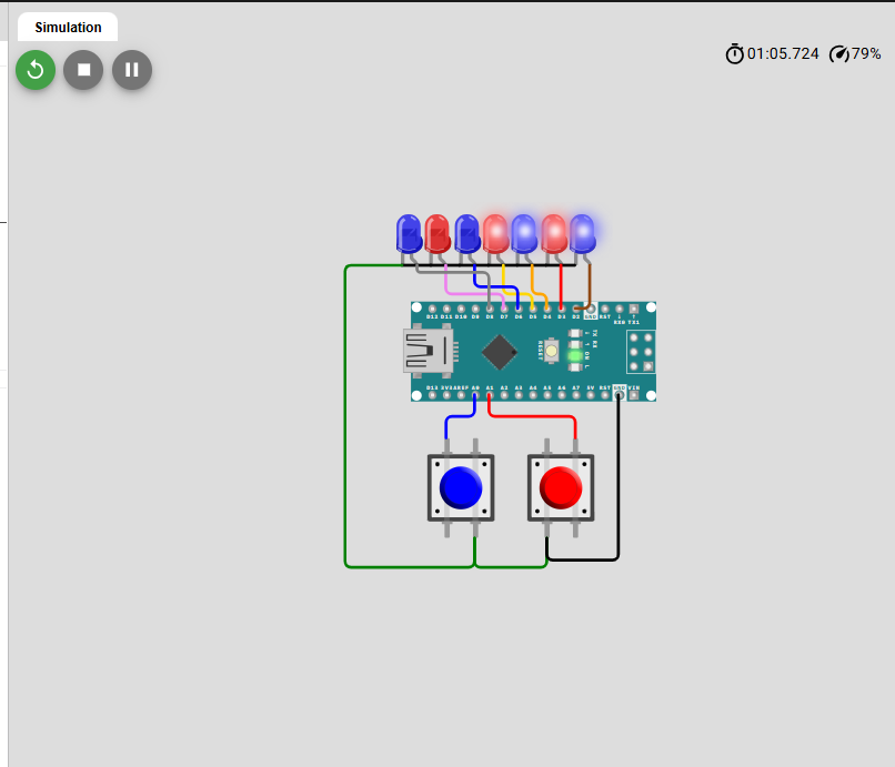
An LED Left and Right Shifter using Arduino Nano is a simple electronics project in which multiple LEDs glow sequentially in different directions. In this project, seven LEDs are connected to the Arduino Nano, and two push buttons are used to control their movement. When the first button is pressed, the LEDs turn ON one by one from left to right, while pressing the second button makes the LEDs glow sequentially from right to left. The Arduino Nano controls the sequence according to the programmed instructions, using loops and an array to manage the LED pins efficiently
Components used
Arduino Nano
Arduino Nano is the main controller. It controls the sequence in which the LEDs turn ON and OFF according to the program. It reads the input from the two push buttons and performs the required action. When one button is pressed, it activates the LEDs from left to right, while the other button activates them from right to left. Its small size and easy programming make it suitable.
Push Buttons
Two push buttons are used to control the direction of the LED sequence in the circuit. The first push button is programmed to start the LED shifting sequence in one direction, while the second button starts the sequence in the opposite direction. When a button is pressed, the Arduino detects the input signal and executes the corresponding LED pattern.
Led’s
Seven LEDs are used as the output devices in this project. Each LED is connected to a separate digital pin of the Arduino Nano through a current-limiting resistor. The LEDs are programmed to glow one after another, creating a shifting effect. Depending on which push button is pressed, the sequence moves either from left to right or right to left.
LED Left and Right Shifter