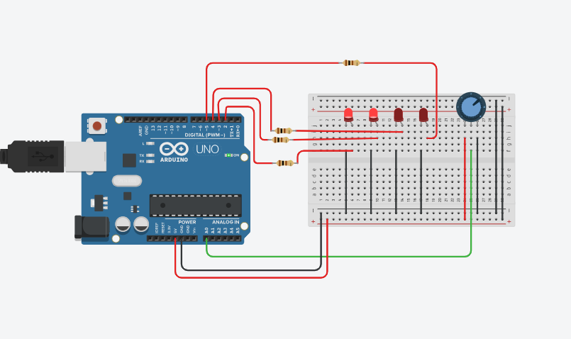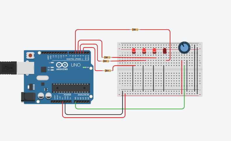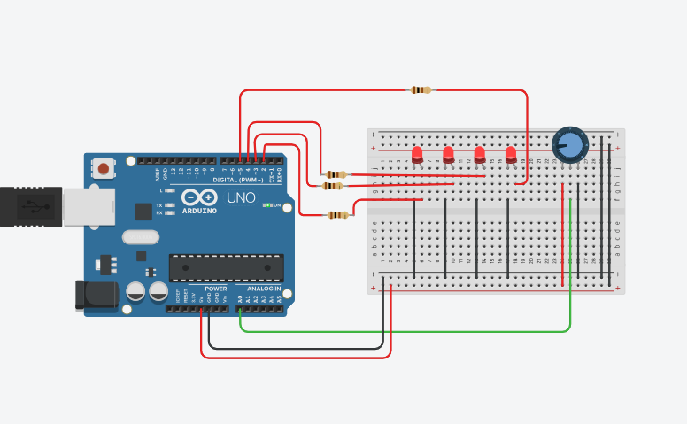
The **Arduino-Based Battery Level Monitoring and Indication System** is an electronic project designed to monitor the voltage level of a battery and represent its approximate charge level using multiple LEDs. An Arduino Uno reads the voltage through its analog input and processes the measured value to determine whether the battery level is low, medium, high, or full. The LEDs provide a simple visual indication of the battery condition, with additional LEDs turning on as the measured voltage increases.
Battery Level Indicator Circuit Diagram

Components used in battery Level indicator
There are Following Components used in battery Level Indicator.
Arduino Uno
The Arduino Uno is the main controller of the project. It reads the voltage from the battery through the voltage divider connected to its A0 analog pin. It then processes the reading and determines the battery’s approximate voltage/level before controlling the LEDs.
Potentiometer
The potentiometer is used to simulate a changing battery voltage in the Tinkercad simulation. Its Terminal 1 is connected to 5V, Terminal 2 to GND, and the wiper to A0. Rotating the potentiometer changes the voltage reaching A0, allowing different battery levels to be simulated.
LED’s
Four LEDs are used to indicate the different levels of the simulated battery. The LEDs provide a visual representation of the voltage measured by the Arduino. As the input voltage increases, additional LEDs turn on. For example, one LED can represent a low battery level, two LEDs can represent a medium level, three LEDs can indicate a high level, and all four LEDs can indicate a full or maximum level.
Here is the Working of Battery Level indicator.