24V–12V Voltage Step-Down Converter
A buck converter is a DC-DC power converter used to step down a higher DC voltage to a lower DC voltage. In a 24 V to 12 V buck converter, the input voltage of 24 V DC is reduced to a regulated output of 12 V DC. The converter uses a high-speed switching device such as a MOSFET, along with an inductor, diode, and capacitor to control and smooth the output voltage. By adjusting the PWM duty cycle, the output voltage can be controlled. For an ideal buck converter, a 50% duty cycle converts 24 V to approximately 12 V. Buck converters are commonly used in power supplies, battery-powered systems, electric vehicles, and industrial automation.(More Projects)
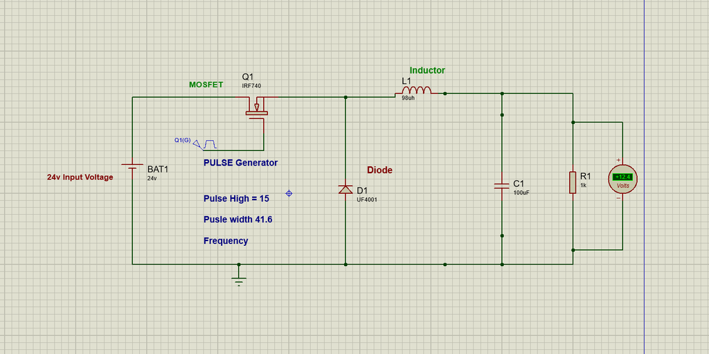
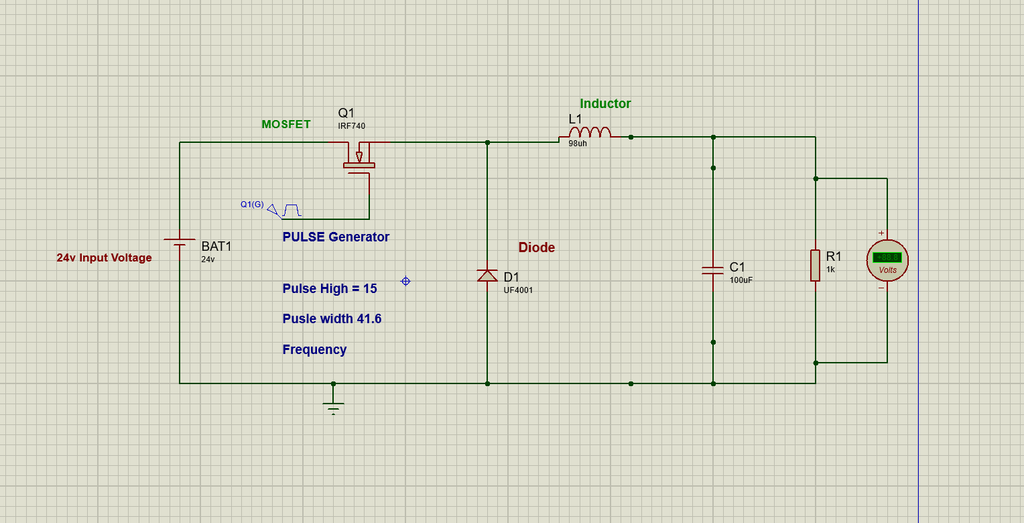
Circuit Diagram of 24 to 12 volt Buck Convertor
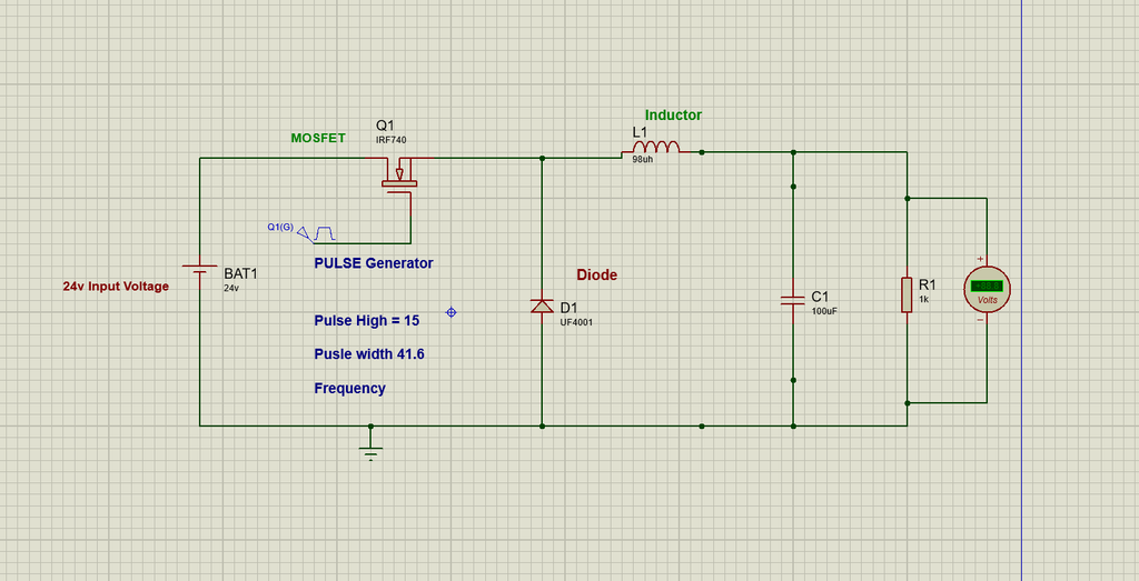
Components used in 24 to 12 volt DC to DC Step down Buck Convertor.
Here are the several components used in the circuit of DC to DC buck convertor.
MOSFET Transistor
The MOSFET works as a high-speed electronic switch. It does not continuously reduce the 24V voltage. Instead, it rapidly switches the input voltage ON and OFF.It controls the energy transfer from the 24V source to the inductor by switching at high speed.The MOSFET therefore converts the constant 24V input into a rapidly switched waveform.
Inductor
The inductor is one of the most important components in the buck converter. It stores electrical energy in its magnetic field when current flows through it.
The inductor current increases and energy is stored in its magnetic field.When the MOSFET turns OFF, the inductor tries to maintain the current flowing through it. In a conventional buck converter, this current continues through the freewheeling diode.
Capacitor
The capacitor is connected across the output/load and is used for filtering.The output of the MOSFET switching stage is not a perfectly smooth DC voltage. It contains voltage variations called ripple.The capacitor charges and discharges to reduce these variations:
Resistor
The resistor is a Passive Element which represents the electrical load connected to the output of the buck converter.
Pulse Generator
The pulse generator acts as the switching-control signal and determines the amount of energy transferred from the input to the output.
Voltmeter
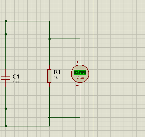
The voltmeter is connected in parallel across the load resistor to measure the output voltage of the buck converter. It displays the voltage obtained after stepping down the input voltage from 24 V DC to approximately 12 V DC. This measurement allows us to verify that the buck converter is providing the desired output voltage across the load.
Best Voltmeters( Click Here)
24v DC to 12v DC Step Down Buck Convertor