
How to create a line following Robot step by step process.
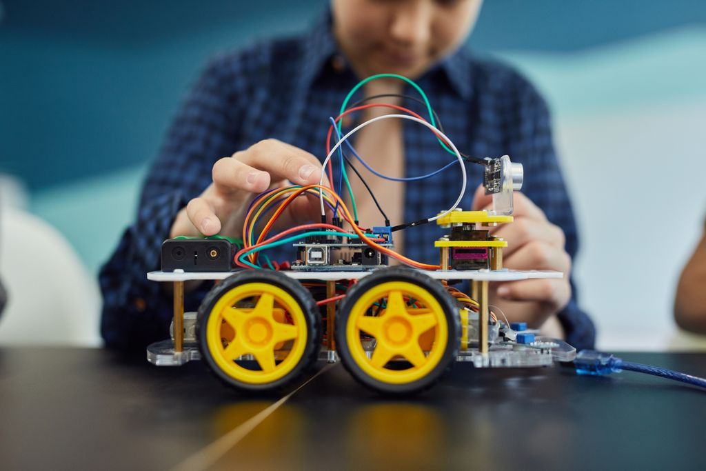
Building a line-following robot is a straightforward and rewarding project. It operates using frequency signals transmitted and received by IR sensors. Whether you’re a student tackling a science project or a hobbyist exploring robotics, this project is both simple to design and highly satisfying to complete within a weekend.
At its core, a line following robot uses infrared sensors to detect the contrast between a dark line. Usually black electrical tape and the lighter floor beneath it. The IR emitter emits the high frequency infrared waves downward after that the receiver measures how much bounces back. Dark surfaces absorb more light, while bright surfaces reflect it.
The 8-array IR sensor module gives the robot eight detection points spread across its width. This lets it sense not just whether it’s on the line, but exactly where it sits relative to the line (far left), slightly left, centered, slightly right, or far right. That positional error is the raw data fed into the PID algorithm, which then decides how to adjust the motor speeds.
What are the components Required to design a Line following Robot.
Microcontroller
Microcontroller act as the brain of the LFR where the whole logic of the code is stored it controls all the operation of the LFR like when to turn Left, Turn Right and when to stop.
there are several cases on the basis of which you have to select your suitable microcontroller.
- Arduino Nano: If you want to just create simple LFR.(cheapest)
- Arduino UNO: If you want to detached the microcontroller after one project.(expensive then Nano & esp-32)
- ESP-32: Best for enhancement like if you want to improve your LFR.it contain build in WIFI.(Less expensive)
Sensors
Sensors act as the eyes of a robot, detecting data in various forms and providing information to the microcontroller. Based on this data, the microcontroller performs specific actions. In Line Following Robots (LFR), Infrared (IR) sensors are commonly used. These sensors measure data by emitting infrared waves and detecting distances.
There are many types of IR sensors, but two are most commonly used in LFRs:
- QTR array 8-in-1 channel IR sensor
- 2x single IR sensors
Motor Drivers
A motor driver is an electronic circuit/module that allows a microcontroller to control a motor by providing high current and make the mottors to run in a controlled speed (PWM).
In LFR’s we mostly use L298 motor drivers. it is a dual H-bridge driver capable of running two DC motors
independently, up to 2A each.
Wheels
The wheels are an important part of LFR which provides Mechanical support to the LFR and helps the Robot in it movement.
Mostly we use three wheels in LFR’s.
- Caster Wheels: Placed at the front side of the cassis. it help the LFR to Move in all direction.
- Wheel attached to Motors: These wheels are controlled wheels they provide controlled.
Chassis
The chassis is the main body or frame of a Line Following Robot (LFR). It holds all the components together and provides the mechanical structure on which the motors, wheels, sensors, battery, and electronics are mounted.
jumper Wires
Jumper wires are used to make electrical connections between the different components of a Line Following Robot (LFR). They connect components such as the Arduino Nano, QTR sensor array, L298N motor driver, motors, and battery
Battery
The battery is the power source of a Line Following Robot. It supplies electrical energy to the motors and electronic components such as the Arduino Nano, QTR sensor array, and L298N motor driver.
in LFR’s mostly we use 2×1860 3.7v Li-ion batteries.
Switch
A switch is used to turn the Line Following Robot ON and OFF without disconnecting the battery.
Wiring connection of Line following Robot
| Arduino Pins | Sensor Pins |
| VCC | Vcc |
| GND | Gnd |
| 2 | 1 |
| 3 | 2 |
| 4 | 3 |
| 8 | 4 |
| 9 | 5 |
| 12 | IR |
| A0 | 6 |
| A1 | 7 |
| A2 | 8 |
Common Mistakes to avoid When building a Line following Robot.
Building a line following robot (LFR) can be an exciting and rewarding project, but even small mistakes can lead to poor performance or complete failure. One of the most common mistakes beginners make while building an LFR includes.
Wrong IR Sensor Selection or Placement
Choosing the wrong type of IR sensors or placing them at an incorrect distance from the surface directly affects the robot’s ability to detect the line accurately.
Ignoring Motor Driver Ratings
Using a motor driver that cannot handle your motor’s current rating can cause overheating or unstable movement.
Unstable Power Supply
Neglecting a clean and stable power supply can introduce noise and cause erratic behavior in the microcontroller.
Unoptimized Code Without PID Control
Writing untuned code without implementing PID control often results in a robot that overshoots or wobbles along the path.
Poor PCB Layout or Loose Wiring
A messy breadboard setup or weak solder joints can create intermittent connections that are extremely difficult to debug.By being aware of these common pitfalls from the start, you can save time, reduce frustration, and build a line following robot that performs reliably every time.
FAQ( Frequently Asked Questions )
How Does a Line Following Robot Work?
A line following robot uses IR sensors to detect contrast between a line (usually black) and the surface (usually white). The sensors send signals to the Arduino, which processes them and adjusts the motor speeds to keep the robot on track. The whole process happens continuously in real time.
What Are the Components Used in Line Following Robots?
A basic LFR needs Following components.
- Arduino board
- IR sensors (QTR array 8 in 1 or 2xsingle IR sensor)
- motor driver (L298N or L293D)
- DC gear motors
- battery pack
- wheels
- chassis
Which Arduino Board is Best for Line Following Robots?
The Arduino Uno/Nano is the best choice for beginners due to its simplicity and strong community support. For more sensors and complexity, go with the Arduino Mega, and for compact builds, the Arduino Nano is ideal. The right board depends on your project’s size and requirements.
What is PID Control?
PID stands for Proportional, Integral, and Derivative. It’s a feedback algorithm that continuously measures error and adjusts the output to keep a system accurate and stable. It’s one of the most widely used control techniques in robotics and industrial automation.